
SKU-1 runs the motor; DG32-LITE can switch its bridge off without firmware.
The motor controller and safety supervisor address different responsibilities. Assess both against the drive, its operating conditions and the consequences of failure.
- BLDC motor controllerRuns the motor: fans, appliances, EV two- and three-wheelers, robotics and actuator joints.
- DG32-LITE safety microcontrollerSupervises the motor: motor-safety supervision, robot joints, and the field-oriented-control processor beside SKU-1.
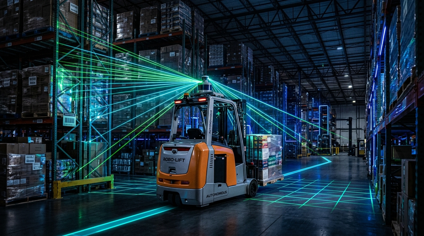
Concept render of an autonomous forklift in a warehouse aisle
The drive and its safety supervisor are separate chips, so a fault in one cannot silence the other.
A motor drive is a loop: measure phase current and rotor position, compute the next voltage, switch the bridge. It runs thousands of times a second, and the power stage it drives can destroy itself in microseconds.
The two chips answer different questions. One keeps the loop running in hardware; the other checks that the processor computing it has not gone wrong, and can turn the bridge off without asking firmware.
- SensePhase current and rotor angle from Hall sensors or an encoder
- Control: SKU-1Hardware PID, CORDIC and Park transforms close the loop in under 1 µs
- DrivePWM and pre-drivers switch the three-phase bridge
- Supervise: SKU-4A trailing core compares every result; a mismatch drives FAULT_N
- Safe stateFAULT_N removes the gate-driver enable and the motor coasts
Three phases, 120° apart, drive the stator coils; the rotor follows the rotating field.
The motor the chips run and supervise
Three phase windings around a magnet rotor: SKU-1 drives them, DG32-LITE watches the drive and can shut it down.
Two chips, each with one job here.
What each part does in this system, and where it stands today.
BLDC motor controller
Runs the motor: fans, appliances, EV two- and three-wheelers, robotics and actuator joints. Replaces: A DRV83xx-class gate driver plus an external MCU, collapsed onto one die with runtime star or delta selection; in fans and appliances, the imported motor-control MCU on every BLDC board.
Open the SKU-1 pageDG32-LITE safety microcontroller
Supervises the motor: motor-safety supervision, robot joints, and the field-oriented-control processor beside SKU-1. Replaces: Functional-safety microcontrollers of the Microchip and Renesas class.
Open the SKU-4 pageFour ways this system fails, and the block that catches each.
The failure modes this system has to survive, and the part of the design that answers each one.
Shoot-through in the bridge
Both switches of a leg on at once. Dead time inserted in the PWM engine prevents it, and must hold as gate thresholds drift with temperature.
A wrong value, silently computed
A transient flips a result inside the processor. Self-test runs too rarely to see it; DG32-LITE’s lockstep pair catches it on the store where it happens.
Noise from the power stage
Fast switching edges couple into the current measurement. Guard rings and separate grounds keep the ADC clean on a shared die.
Wear that has not failed yet
Bearing and winding faults show in the current the drive already samples. Small classifiers can flag them in the cycles the loop leaves free.
Evidence today: one chip is FPGA-validated, one is at design stage.
- SKU-1, BLDC motor controller: FPGA-validated: the motor control datapath runs as circuit code on an Artix-7 at 81.25 MHz.
- SKU-4, DG32-LITE safety microcontroller: Simulation and implementation records; no measured silicon result published.
DG32 in this application, explained
Narrated films on the DG32 safety path and architecture, with captions.
Send the system and its numbers; the reply maps them to each part.
The motor, its power and speed range, the control loop rate and the sensing you have are what we need to answer.