
Three parts for screened platforms: 28 V power rails, a GPS-free drone SoC and a rugged display driver.
Defence, aviation and drone programmes need both a suitable component and the evidence required for their operating environment. Country of origin does not replace performance or qualification.
- D100 drone SoCFlight control and visual-inertial navigation for drones, with a hardware failsafe to the speed controllers. Navigation is geometric, so it does not depend on GPS; jamming immunity is not yet established.
- High-reliability power ICThe sequenced 28 V power rails of avionics and military-vehicle electronics.
- Rugged display driverRugged and industrial displays; a wider-temperature version for cockpits.
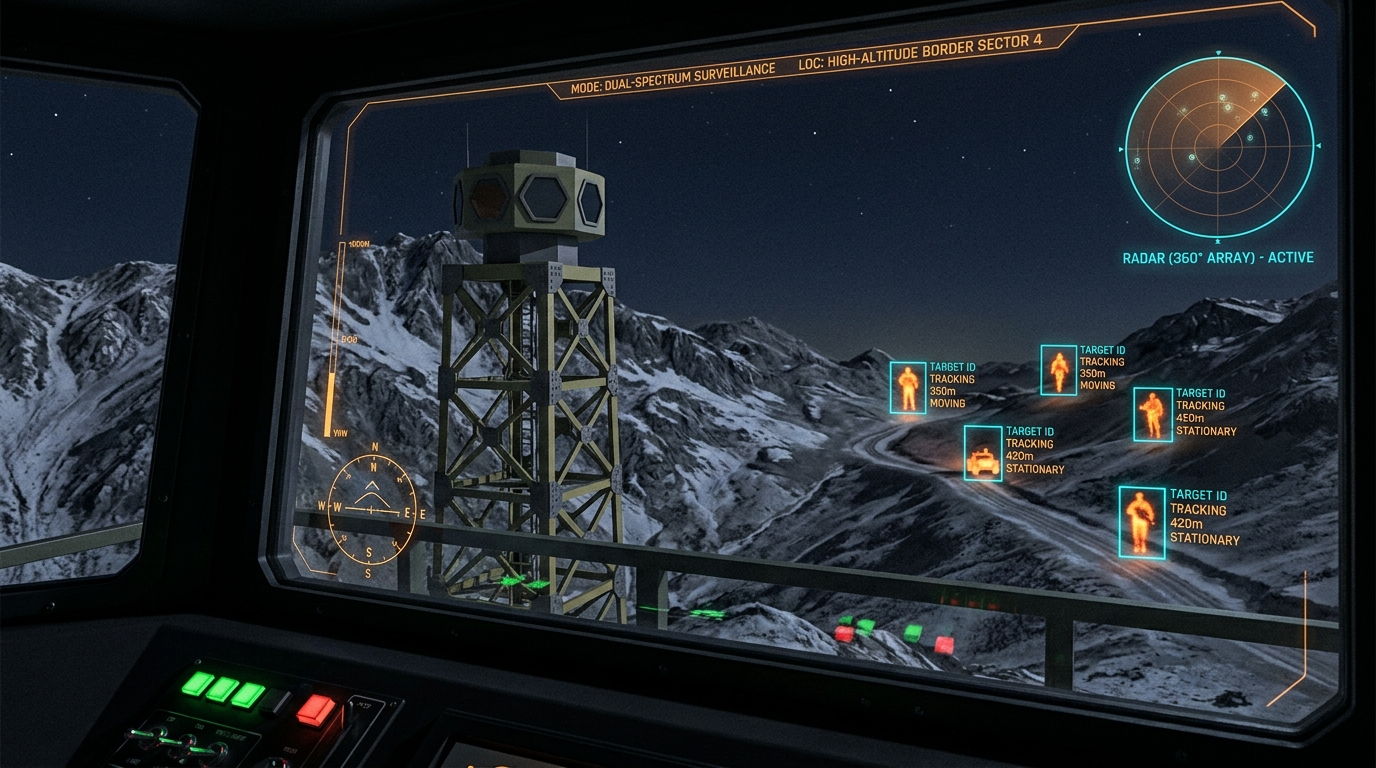
Concept render of a border surveillance tower seen from an operator cabin
Each part answers one physical requirement of a screened platform: surge, upset, a hung stack or a frozen display.
Drones, avionics boxes and rugged vehicles share a hostile electrical and physical environment: a 28 V bus with surges, radiation at altitude, heat in a closed fuselage, and displays read in direct sun. The requirement differs by platform, and each has its own qualification route.
The parts here cover the chain from the power bus to the operator: clean, sequenced rails, a flight or mission controller that fails safe in hardware, sensing that works without GPS, and a display that notices when it has frozen.
- Power: SKU-328 V bus to four sequenced rails, surge-tolerant and upset-hardened
- Sense: SKU-777 GHz radar for obstacles and terrain
- Fly: D100Flight control and GPS-denied navigation, with a separate failsafe island
- Check: SKU-4Lockstep supervision of flight-critical computation
- Show: SKU-8Cockpit display with sunlight gamma and frame-freeze detection
Five chips, each with one job here.
What each part does in this system, and where it stands today.
D100 drone SoC
Flight control and visual-inertial navigation for drones, with a hardware failsafe to the speed controllers. Navigation is geometric, so it does not depend on GPS; jamming immunity is not yet established. Replaces: Qualcomm’s QRB5165, the closest comparable chip, which is imported. Most chips in this class do AI or flight control, not both.
Open the D100 pageHigh-reliability power IC
The sequenced 28 V power rails of avionics and military-vehicle electronics. Replaces: TI and ADI QML power parts in avionics and vetronics units; imported EN 50155-grade power parts in Indian rolling stock and signalling; imported radiation-tolerant PMICs on Indian satellites and launchers.
Open the SKU-3 pageRugged display driver
Rugged and industrial displays; a wider-temperature version for cockpits. Replaces: Imported timing-controller and column-driver chipsets in rugged and industrial displays.
Open the SKU-8 page77 GHz 4D radar
Defence perimeter and counter-drone radar. Replaces: Imported 77 GHz radar front ends and the processing chips that go with them.
Open the SKU-7 pageDG32-LITE safety microcontroller
Flight-critical redundancy feeding the D100 roadmap. Replaces: Functional-safety microcontrollers of the Microchip and Renesas class.
Open the SKU-4 pageFour ways this system fails, and the block that catches each.
The failure modes this system has to survive, and the part of the design that answers each one.
A 100 V surge on the bus
An inductive load dump spikes the 28 V bus. The power IC’s input stage has to clamp it without thermal runaway in its own pass devices.
A particle flips a bit
At altitude a single upset can corrupt a state machine. Interlocked latches and triple redundancy keep the power sequence correct.
The mission computer hangs, or GPS is jammed
D100’s failsafe island watches from outside the flight stack and can take the motors to a safe state on its own.
The display freezes
A frozen picture looks normal. Frame-by-frame CRC comparison flags it within two frames.
Evidence today: one chip is FPGA-validated, four are at design stage.
- D100, D100 drone SoC: FPGA-validated: the drone position engine runs as circuit code on the same Artix-7.
- SKU-3, High-reliability power IC: Architecture diagram in the SKU Blueprint; prototyping planned on sky130 20 V devices, production at SCL 180 nm.
- SKU-8, Rugged display driver: Architecture diagram and status in the SKU Blueprint.
- SKU-7, 77 GHz 4D radar: Architecture diagram and status in the SKU Blueprint. The SiGe front end has no FPGA equivalent, so it is proven on silicon or not at all.
- SKU-4, DG32-LITE safety microcontroller: Simulation and implementation records; no measured silicon result published.
Send the system and its numbers; the reply maps them to each part.
The platform, its power bus, environment and screening route, and what must keep working when software fails, are what we need to answer.