
SKU-6 · SCL 180 nm CMOS; sky130 prototype Quad-rail supervisor
SKU-6 watches four supply rails and latches a fault after an 8 µs deglitch.
Every figure on this page is a design target unless marked otherwise.
- Rails
- 5.0, 3.3, 1.8 and 1.2/0.9 V adjustable
- Deglitch
- 8 µs digital filter
- Watchdog
- Windowed, 100 ms to 1.6 s
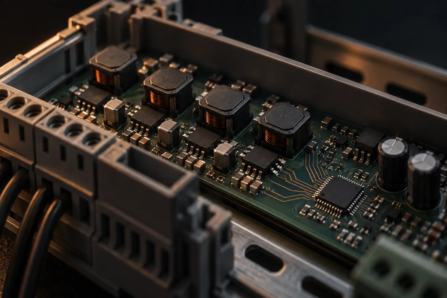
SKU-6 watches four supply rails and latches a fault after an 8 µs deglitch.
SKU-6 watches supply conditions and records a fault so the wider system can respond. It targets a function needed across many boards.
- Job
- Detect unsafe supply conditions and latch a fault.
- Replaces
- Supervisor chips from TI and Maxim, which sit on almost every circuit board.
- Status
- RTL ready for the digital logic; comparators and reference designed and simulated. Prototype on sky130, production on SCL 180 nm.

The business case for SKU-6
Define which power disturbances should stop the system and which should be tolerated.
What it replaces
Supervisor chips from TI and Maxim, which sit on almost every circuit board.
Customer opportunity
Defence grade: every defence electronics unit and every D100 module. Commercial grade: one or more on nearly every circuit board, the highest unit count in the range.
Policy and demand
The simplest chip in the range, so it goes through military screening first and sets up the qualification flow for every defence part behind it.
The delivery trade-off
Accurate thresholds from −40 to +125 °C come from a trimmed reference and matched resistors, a strength of mature nodes.
What SKU-6 claims, what it is worth, and what gates it.
The following mechanisms explain the proposed customer benefit. Each still needs to be validated in the complete product.
SKU-6 watches four supply rails and latches a fault after an 8 µs deglitch.
SKU-6 watches supply conditions and records a fault so the wider system can respond. It targets a function needed across many boards.
Four rails share one latched FAULT_N; the board decides what each fault stops.
Define which power disturbances should stop the system and which should be tolerated.
The 8 µs deglitch has to be proven against the board’s own supply noise.
The response must be tested against real supply noise and the intended screening requirements.
Architecture targets, not datasheet values.
Every figure is a design target stated in the SKU Blueprint, page 25. None is a measurement of manufactured silicon.
- 8 µsDeglitch filter
- 500 µVComparator offset, at most
- 0.1%Threshold-network matching
Detailed architecture and specifications
- Process
- 130 nm CMOS prototype, 180 nm production
- Rails
- 5.0, 3.3, 1.8 and 1.2/0.9 V adjustable
- Comparator offset
- Under 500 µV, chopper stabilised
- Threshold network
- 0.1%-matched polysilicon, OTP trim
- Deglitch
- 8 µs digital filter
- Reference
- 10 ppm/°C bandgap
- Watchdog
- Windowed, 100 ms to 1.6 s
- Outputs
- Latched FAULT_N, RESET_N after 200 ms
- Process
- SCL 180 nm CMOS; sky130 prototype
- Maturity
- Architecture scope
- Designed toward
- MIL-STD-883K Class B screening flow
- Source
- SKU Blueprint, October 2026, page 25
Standards the architecture is designed toward. No DeepGrid part holds a certification or qualification today.
System architecture, signal flow and engineering references

Marker ①: Each rail enters through its own matched divider
Four rails come in at VIN 1 to VIN 4: 5.0, 3.3, 1.8 and an adjustable 1.2/0.9 V, each behind 2 kV ESD protection. Each feeds its own Divider, a polysilicon ladder matched to 0.1%, so its Comparator sees a scaled copy of the rail whose ratio barely moves with temperature.
Sense chain · one per rail
Marker ②: Only a fault that outlasts 8 µs reaches the matrix
The chopper-stabilised Comparator holds its offset under 500 µV and adds 8 mV of hysteresis. Its output then passes the Deglitch counter, which drops anything shorter than 8 µs. Converter ripple dies there; a real brownout survives the window and reports a confirmed fault to the Fault matrix.
Sense chain · one per railFault logic
Marker ③: The matrix latches the fault and warns before it resets
The Fault matrix is maskable and latched, with a priority encoder and I²C registers that record which rail failed. It drives FAULT_N first, then RESET_N, an open-drain output held for a trimmed 200 ms. A latched fault stays asserted until it is cleared, so the system cannot miss it. MR / manual adds a push-button reset.
Fault logicOutput stage
Marker ④: One trimmed bandgap sets every comparator threshold
Threshold accuracy starts in Reference + timebase. A curvature-corrected Bandgap at 1.20 V and 10 ppm/°C sets all four comparator thresholds, and a 5-bit OTP Trim brings it to ±0.5% once, at test. The Osc block supplies a 1 MHz timebase with a reference current, so the chip keeps its own time.
Reference + timebaseSense chain · one per rail
Marker ⑤: A late or early kick from the processor forces a reset
The Watchdog checks the processor, not the rails. Window logic opens and closes a window adjustable from 100 ms to 1.6 s, and firmware must kick WDI inside it. A kick that comes too early or never comes runs the Timeout counter out, which drives RESET_N in the Output stage, so a hung or runaway processor restarts.
WatchdogOutput stage
Numbered markers
- ①Marker ①: Each rail enters through its divider.
- ②Marker ②: The comparator and deglitch counter report a confirmed fault to the matrix.
- ③Marker ③: The matrix latches it and drives FAULT_N, then RESET_N.
- ④Marker ④: The trimmed bandgap sets every comparator threshold.
- ⑤Marker ⑤: A missed or early watchdog kick times out to RESET_N.
Block responsibilities
- Sense chain · one per rail
For each of four rails: an ESD-protected input, a 0.1%-matched polysilicon divider, a chopper-stabilised comparator with 8 mV hysteresis, and an 8 µs digital deglitch counter.
Why Switching noise must not trip a reset, yet a real fault must still be caught quickly; the deglitch counter does both.
Guide: Sense chain · one per rail- Fault logic
A maskable, latched fault matrix with a priority encoder, mask register, latch and I²C registers.
Guide: Fault logic- Output stage
Open-drain FAULT_N, which asserts before RESET_N, an open-drain RESET_N with a trimmed 200 ms delay, and a manual-reset input.
Guide: Output stage- Reference + timebase
A curvature-corrected bandgap at 1.20 V and 10 ppm/°C, a 5-bit OTP trim to ±0.5%, and a 1 MHz oscillator with a reference current.
Why The bandgap and trimmed polysilicon resistors are what make the threshold accuracy possible on a mature node.
Guide: Reference + timebase- Watchdog
A windowed watchdog adjustable from 100 ms to 1.6 s: an open and close window, a kick input, and a timeout counter that drives RESET_N.
Guide: Watchdog
Primary sources
- SKU-6 architecture guideEvery block group, the data flows and the design targets.Opens in the site
- SKU Blueprint, October 2026SKU-6: what it replaces, who uses it, its status and its architecture diagram.PDF · 46 pages
2 integration and validation references
- A simple three-terminal IC bandgap referenceBrokaw, IEEE Journal of Solid-State Circuits, 1974: the bandgap cell the reference is built on.IEEE · DOI
- Hercules safety MCUs (TI SPRY178)Lockstep CPUs with a cycle offset, and why a watchdog should be windowed.Texas Instruments · PDF
Background reading explains the general technique each block uses. None of it describes this part or implies its certification.
Architecture from the SKU Blueprint, page 25. A functional view, not a floorplan.
7 questions SKU-6 has to answer before it can be relied on.
The Blueprint’s design and status notes raise these. Each is a question silicon, test or layout has to answer before SKU-6 can be relied on.
Thresholds accurate to a fraction of a percent.Physics
Comparators with offset under 500 µV and 0.1%-matched polysilicon dividers trimmed once.
A buck converter’s ripple must not trip it; a real brownout must.Physics
An 8 µs digital deglitch window between the comparator and the latch.
A reference stable over the military temperature range.Physics
A curvature-corrected bandgap at 10 ppm/°C.
Deglitch windowOpen
Is 8 µs long enough to ignore converter noise and short enough to stop memory corruption before reset?
Chopper rippleOpen
What filtering removes the chopper’s own ripple before the fault latch?
Ladder ageingOpen
How far does polysilicon drift move the 0.1% ratio over twenty years at high temperature?
Why this part firstOpen
What does taking SKU-6 through screening first establish for every part that follows?
An architecture, with its evidence named.
- Strongest evidence
- FPGA-validated: the supervisor sensing chain runs as circuit code on the same Artix-7.
- Development status
- RTL ready for the digital logic; comparators and reference designed and simulated. Prototype on sky130, production on SCL 180 nm.
Planned screening pathfinder; the manufacturing route remains to be resolved against the broader roadmap.
How every figure on this site was obtainedThe systems it goes into, and the parts beside it.
Rail thresholds, transient rejection, fault latching and screening.
Parts beside it
Read the source behind every figure.
Each document opens inside the site at the cited section; the PDF is the edition of record.
- SKU Blueprint, October 2026 (11 SKUs + D100)SKU-6, page 25 · source of recordPDF · 46 pages
- Mature-Node Silicon for India’s Defence (Whitepaper v3)Evidence for this partPDF · 71 pages
Design files
Bring the socket. We will tell you what SKU-6 has to prove for it.
Send the platform, voltage and power environment, interfaces and qualification needs. The reply names what is architecture, what is evidence and what would have to be tested.